(Updated 4/11/2018; Click here for a PDF version of this quick guide; Note that the plots shown in this user guide are not necessarily from one particular run/model)
OpenSeesPL is a Windows-based graphical pre- and post-processor (user-interface) for three dimensional (3D) ground and ground-structure response (Lu et al. 2006; Elgamal and Lu 2009). Finite Element (FE) computations in OpenSeesPL are conducted using OpenSees (Mazzoni et al. 2009; McKenna et al. 2010), an open-source software framework developed by the Pacific Earthquake Engineering Research (PEER) Center since 1998.
OpenSeesPL main window:
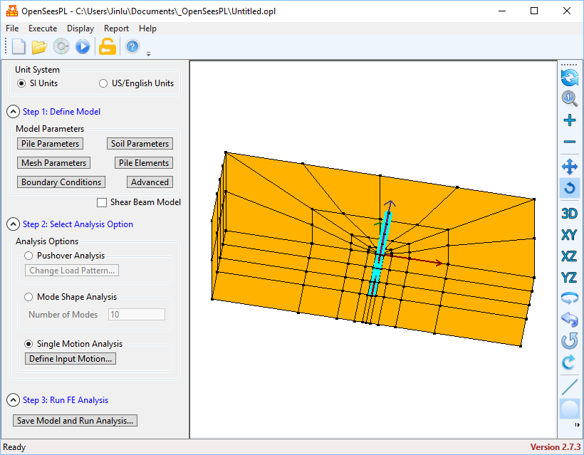
Image buttons in the main window (also available in the deformed mesh window):
![]() : To recreate FE mesh if there is a change in input parameters.
: To recreate FE mesh if there is a change in input parameters.
![]() : To redraw the FE mesh based on the original zoom settings.
: To redraw the FE mesh based on the original zoom settings.
![]() : To zoom in on the FE mesh.
: To zoom in on the FE mesh.
![]() : To zoom out on the FE mesh.
: To zoom out on the FE mesh.
![]() : To pan the view on the FE mesh. This is a toggle button which means it can be turned on or off.
: To pan the view on the FE mesh. This is a toggle button which means it can be turned on or off.
![]() : To rotate the FE mesh. This is a toggle button which means it can be turned on or off. However, this button and the above toggle button (i.e., the one to pan the view) cannot be both ON at the same time. When the user turns on either of them, the other one will be changed to OFF automatically.
: To rotate the FE mesh. This is a toggle button which means it can be turned on or off. However, this button and the above toggle button (i.e., the one to pan the view) cannot be both ON at the same time. When the user turns on either of them, the other one will be changed to OFF automatically.
![]() : To display the 3D view of the FE mesh.
: To display the 3D view of the FE mesh.
![]() : To display the XY-plane view of the FE mesh.
: To display the XY-plane view of the FE mesh.
![]() : To display the XZ-elevation view of the FE mesh.
: To display the XZ-elevation view of the FE mesh.
![]() : To display the YZ-elevation view of the FE mesh.
: To display the YZ-elevation view of the FE mesh.
![]() : To rotate the FE mesh about the vertical axis (Z) counter-clockwise (if viewed from the positive Z-axis).
: To rotate the FE mesh about the vertical axis (Z) counter-clockwise (if viewed from the positive Z-axis).
![]() : To rotate the FE mesh about the vertical axis (Z) clockwise (if viewed from the positive Z-axis).
: To rotate the FE mesh about the vertical axis (Z) clockwise (if viewed from the positive Z-axis).
![]() : To rotate the FE mesh about the longitudinal axis (X) clockwise (if viewed from the positive X-axis.
: To rotate the FE mesh about the longitudinal axis (X) clockwise (if viewed from the positive X-axis.
![]() : To rotate the FE mesh about the longitudinal axis (X) counter-clockwise (if viewed from the positive X-axis).
: To rotate the FE mesh about the longitudinal axis (X) counter-clockwise (if viewed from the positive X-axis).
![]() : To show the pile(s) only if the button is “ON” status (this is also a toggle button).
: To show the pile(s) only if the button is “ON” status (this is also a toggle button).
![]() : To show the pile size/dimensions (in Cyan color) if the button is “ON” status (this is a toggle button).
: To show the pile size/dimensions (in Cyan color) if the button is “ON” status (this is a toggle button).
![]() : To show the X, Y and Z axes of the global coordinate system if the button is “ON” status (this is a toggle button)
: To show the X, Y and Z axes of the global coordinate system if the button is “ON” status (this is a toggle button)
1. Menu
(Go to 2. Model Parameters 3. Analysis Types 4. Miscellaneous)
Menu File
New Model: To create a new OpenSeesPL model. All input parameters will be reset to the default values (and FE mesh will be recreated).
Open Model…: To open an existing OpenSeesPL model file (an OpenSeesPL model file must have an .opl extension).
Save Model: To save the current OpenSeesPL model to file (if there is any change). If the model has not been saved yet, a window will pop up to ask the folder and filename to save the current model. The model filename will be suffixed with the “.opl” extension if not provided.
Save Model As…: To save the current OpenSeesPL model as a different filename (with the .opl extension). The model filename will be suffixed with the “.opl” extension if not provided.
OpenSeesPL allows to conveniently save and open a model file. The model filename must have the .opl extension. No space is allowed in an OpenSeesPL model filename.
When a model file is saved and analysis is about to start, a folder suffixed with “_plfiles” will be created. For example, if the model file is saved as “Untitled.opl”, a folder named “Untitled_plfiles” is created (under the same folder as the model file) and will contain all files associated with the model including OpenSees Tcl and output files, some of which include (Taking “Untitled.opl” model filename as an example):
Untitled.tcl: OpenSees Tcl input file for the OpenSeesPL model.
Untitled.log: OpenSees analysis log file for the model.
Untitled.dsp: OpenSees displacement output file for all nodes.
Untitled.acc: OpenSees acceleration output file for all nodes.
Untitled.piledisp: OpenSees displacement output file for all pile nodes.
Untitled.pileforce: Internal force output file for all pile elements.
Exit: To exit OpenSeesPL.
Menu Execute
Save Model and Run Analysis: To save the current model and run OpenSees analysis. A popup will be displayed to show the analysis progress.

If the analysis fails (typically due to convergence problems) in the final run (i.e., after application of own weight), OpenSeesPL should be able to view the results up to the step where the analysis fails.
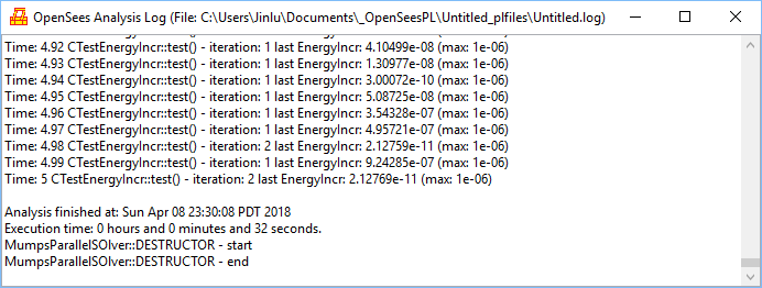
OpenSees Analysis Log: To view OpenSees analysis log (if any) for the current model. If the model file is named “Untitled.opl”, the OpenSees log file will be “Untitled.log” (located under the folder of “Untitled_plfiles”).
Menu Display
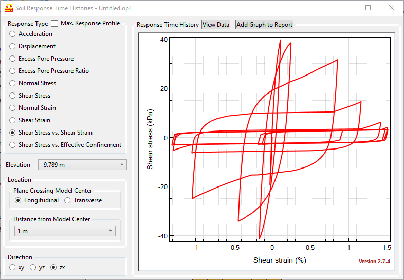
Soil Response Time Histories: To view the response time histories of the soil. A zero-depth/elevation means the ground surface. If Max. Response Profile is checked, the absolute maximum values of the response along the depth/elevation will be displayed.
Deformed Mesh: To view the deformed mesh.
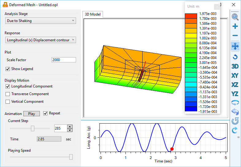
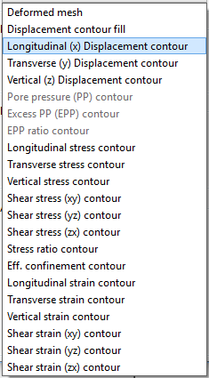
List of the response items available in the deformed mesh window (may not be all available depending on the problem/model being analyzed):
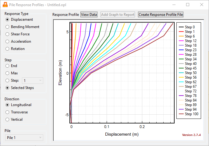
Pile Response Profiles: To view the response profiles of the pile (or a given pile for a pile group case). A zero-elevation is the elevation at the ground surface. If End is selected, the response profile at the end of analysis will be displayed. If Max is selected, the response profile at the time when the absolute maximum of the response (across the entire given pile) is reached, will be displayed. If Selected Steps is chosen, response profiles for about 20 steps including step 0, step 1 and the final step will be displayed.
Notes:
If Bending Moment and Longitudinal are chosen, the bending moment displayed is the one about the Y-Transverse axis (Myy).
If Bending Moment and Transverse are chosen, the bending moment displayed is the one about the X-Longitudinal axis (Mxx).
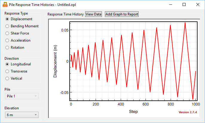
Pile Response Time Histories: To view the response time histories for the pile (or a given pile for a pile group case).
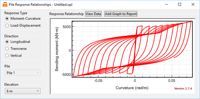
Pile Response Relationships: To view the bending moment-curvature and force-displacement curves for the pile (or a given pile for a pile group case) at a given elevation. Note that a zero-elevation is the elevation at the ground surface.
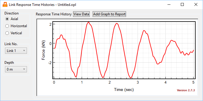
Link Response Time Histories: To view the response time histories of a given rigid link (connecting between soil and pile elements).
Postprocessing Settings: To change postprocessing settings.
Menu Report
(Microsoft Word is required for this menu to be functional)
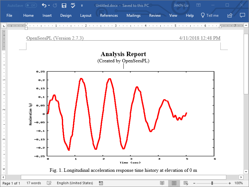
Open Report Session: To open a report session. When a report session is open, a .docx Word file is created (e.g., Untitled.docx under folder “Untitled_plfiles” if the model file is named “Untitled.opl”) and the user can add figures (which will be converted to PNG images) to the Word file until the report session is closed (see the menu item to be described next). The Word file will be overwritten (if exists) when a new report session is open.
Close Session and Open Report: To close session and Open the report file (in Microsoft Word).
Menu Help
OpenSeesPL Website: To go to OpenSeesPL website (http://soilquake.net/openseespl/).
About OpenSeesPL: To view OpenSeesPL copyright and other information.
2. Model Parameters
(Go to 1. Menu 3. Analysis Types 4. Miscellaneous )
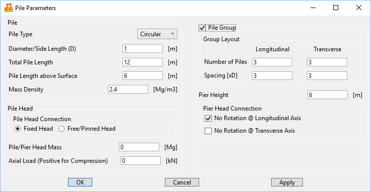
Pile Parameters:
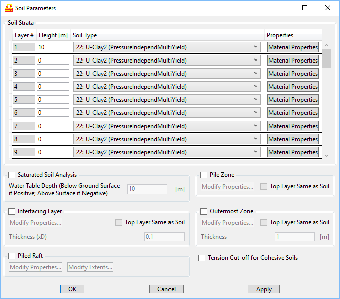
Soil Parameters:
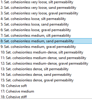
Built-in materials (Yang and Elgamal 2002; Elgamal et al. 2003; Yang et al. 2003):
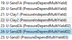
User-defined soil materials (Yang and Elgamal 2002; Elgamal et al. 2003; Yang et al. 2003):
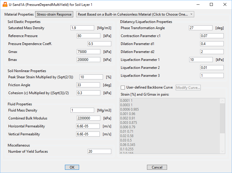
USand1A:
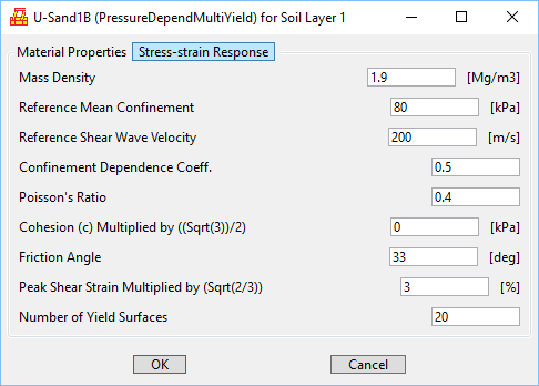
USand1B:
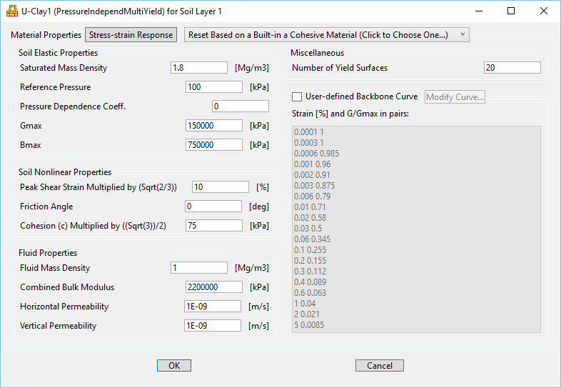
UClay1:
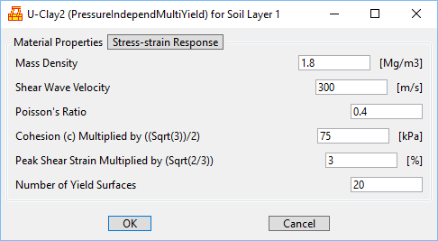
UClay2:
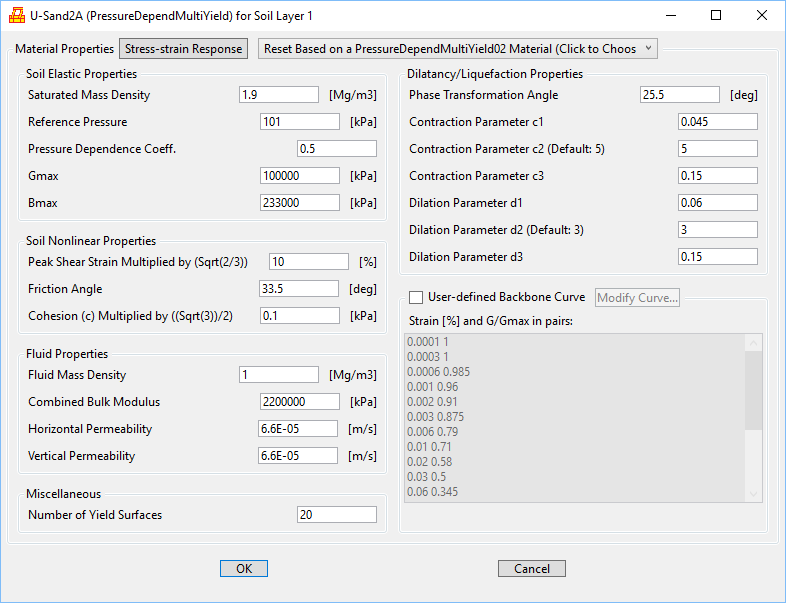
USand2A:
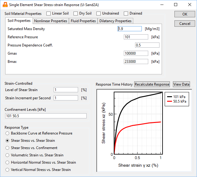
Shear-stress strain response of single element:
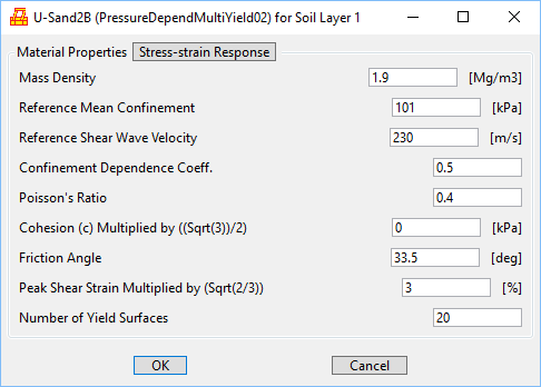
USand2B:
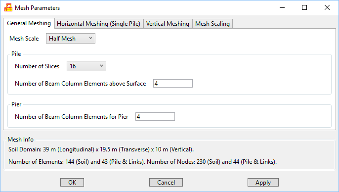
Mesh Parameters:
Horizontal meshing parameters for the single pile case:

Horizontal meshing parameters for a pile group case:
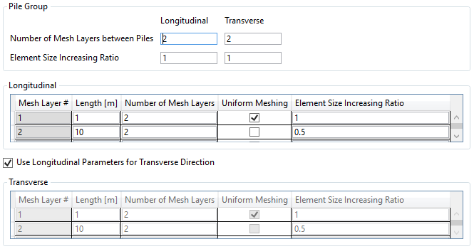
Vertical meshing parameters:

Mesh scaling:

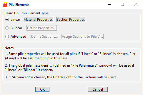
Pile Elements:
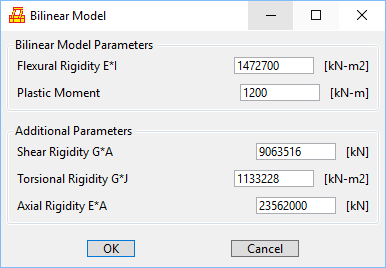
Bilinear pile model:
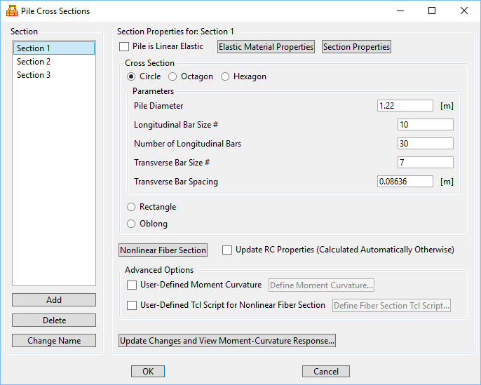
Nonlinear Fiber section (Scott and Fenves 2006; Scott and Ryan 2013):
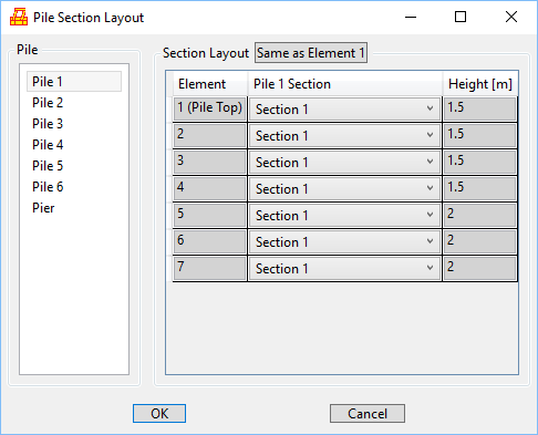
Assigning sections to pile(s):
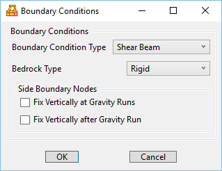
Boundary Conditions:
Advanced:
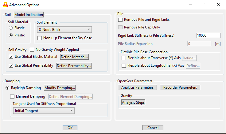
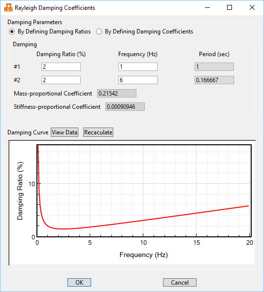
Rayleigh damping:
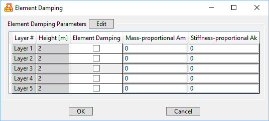
Element damping:
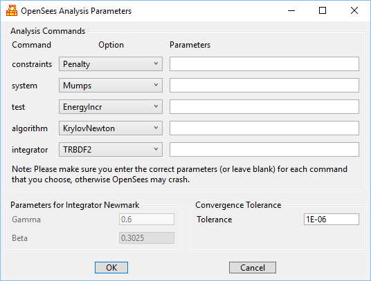
Analysis parameters:
Shear-beam type site response analysis:
Shear-beam model can be obtained by checking “Shear Beam Model” in the OpenSeesPL main window:

3. Analysis Types
(Go to 1. Menu 2. Model Parameters 4. Miscellaneous )
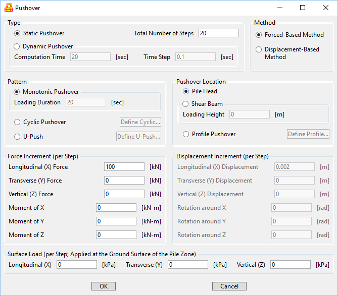
Pushover Loading (Pushover Analysis is available only when pile is included)
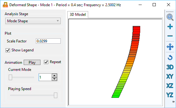
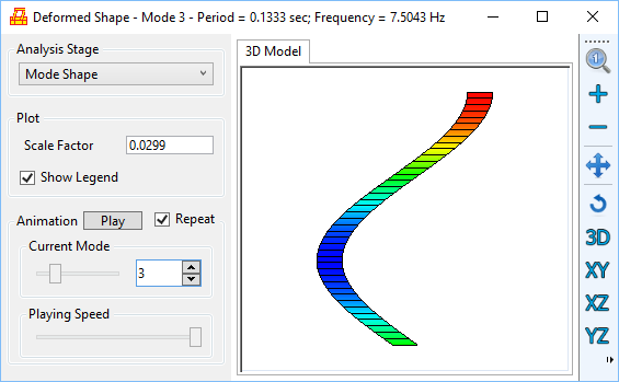
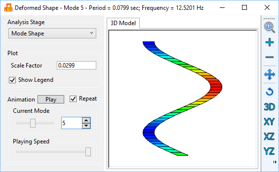
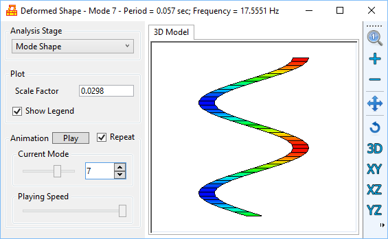
Mode Shape Analysis:
First few modes for a shear beam model (the mode shapes are displayed in the deformed mesh window):
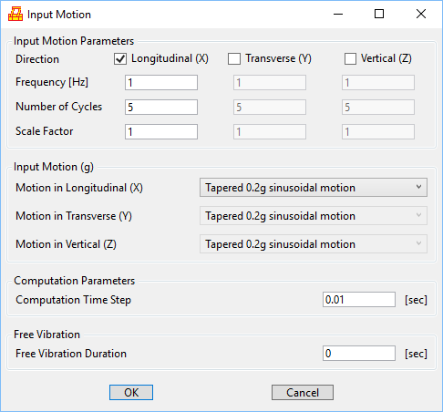
Base Shaking:
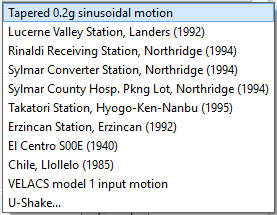
List of built-in input motions and also option to define user input motion:
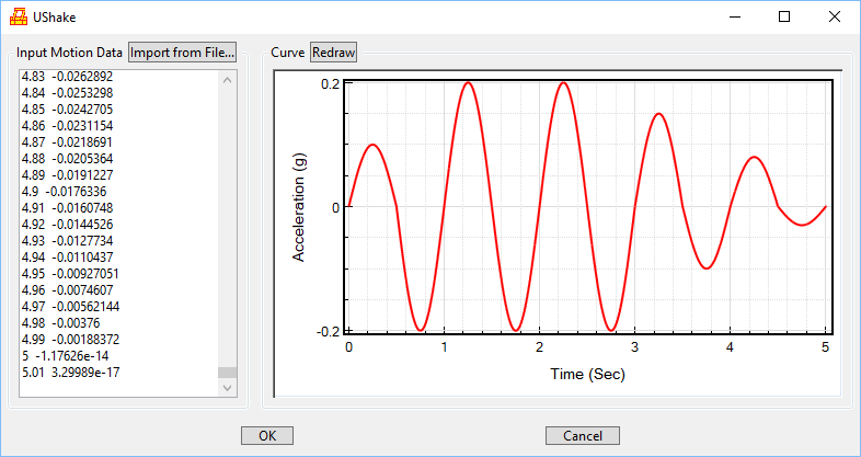
User-defined input motion (time and acceleration in g):
4. Miscellaneous
(Go to 1. Menu 2. Model Parameters 3. Analysis Types)
(i) Regarding Modifying OpenSees Tcl Files
It is possible that OpenSeesPL is still able to do post-processing if the user modifies the OpenSees Tcl files manually (in this case, analysis cannot be performed through the user interface but instead has to be done in the OpenSees command window). However, care must be taken if the user plans to make changes to the Tcl input files. Only minor modifications of the Tcl files are suggested and change of the mesh information (e.g., adding/removing nodes/elements) is discouraged.
(ii) Regarding Unit Systems
OpenSeesPL operates in SI and English units. The SI unit system in OpenSeesPL uses m, kN, kPa, Mg, etc. The English one uses inches (or feet), kips, psi, pcf, and so on.
Note that in OpenSeesPL, the output recorded in the OpenSees recorder files (e.g., Untitled.dsp) are in SI units (even the English unit system is selected). Conversion is done internally in OpenSeesPL for the post-processing, if the English unit system is being used.
References
Elgamal, A., Yang, Z., Parra, E., and Ragheb, A. (2003). “Modeling of cyclic mobility in saturated cohesionless soils.” International Journal of Plasticity, 19(6), 883-905.
Elgamal, A., and Lu, J. (2009). “A framework for 3D finite element analysis of lateral pile system response.” Geotechnical Special Publication No. 186, 616–623.
Khosravifar, A., Elgamal, A., Lu, J., Li, J. (2018). “A 3D model for earthquake-induced liquefaction triggering and post-liquefaction response.” Soil Dynamics and Earthquake Engineering, 110, 43-52.
Lu, J., Elgamal, A., and Yang, Z. (2006). “OpenSeesPL three-dimensional lateral pile-ground interaction version 1.0 user manual.” Report No. SSRP-06/04, Dept. of Structural Engineering, Univ. of California, San Diego.
Mazzoni, S., McKenna, F., Scott, M. H., Fenves, G. L., et al. (2009). Open System for Earthquake Engineering Simulation, User Command-Language Manual, Pacific Earthquake
Engineering Research Center, University of California, Berkeley, OpenSees version 2.0, May.
McKenna, F., Scott, M., and Fenves, G. (2010). “Nonlinear Finite-Element Analysis Software Architecture Using Object Composition”. J. Comput. Civ. Eng., 24(1), 95–107.
Scott, M.H. and G.L. Fenves. (2006). “Plastic Hinge Integration Methods for Force-Based Beam-Column Elements”, Journal of Structural Engineering, 132(2), 244-252.
Scott, M.H. and K.L. Ryan. (2013). “Moment-Rotation Behavior of Force-Based Plastic Hinge Elements”, Earthquake Spectra, 29(2), 597-607.
Yang, Z., and Elgamal, A. (2002). “Influence of permeability on liquefaction-induced shear deformation.” Journal of Engineering Mechanics, 128(7), 720-729.
Yang, Z., Elgamal, A., and Parra, E. (2003). “A computational model for cyclic mobility and associated shear deformation.” Journal of Geotechnical and Geoenvironmental Engineering, 129(12), 1119-1127.
